T-MAG™ pumps are designed to meet the performance requirements of even the most demanding pumping applications. They have been designed and manufactured to the highest standards and are available in a variety of liquid path materials to meet your chemical resistance needs. Refer to the performance section of this manual for an in-depth analysis of the performance characteristics of your pump. The suction pipe size should be at least the equivalent or larger than the diameter size of the suction inlet on your T-MAG™ mag drive pump . The suction hose/pipe must be non-collapsible. Discharge piping should also be the equivalent or larger than the diameter of the pump discharge which will help reduce friction losses. It is criticalthat all fittings and connections are airtight to reduce the risk of cavitation which may damage the pump.
INSTALLATION: Months of careful planning, study, and selection efforts can result in unsatisfactory pump performance if installation details are left to chance. Premature failure and long term dissatisfaction can be avoided if reasonable care is exercised throughout the installation process.
LOCATION: Noise, safety, and other logistical factors usually dictate where equipment will be situated on the production floor. Multiple installations with conflicting requirements can result in congestion of utility areas, leaving few choices for additional pumps. Within the framework of these and other existing conditions, every pump should be located in such a way that 8 key factors are balanced against each other to maximum advantage.
ACCESS: First of all, the location should be accessible. If it’s easy to reach the pump, maintenance personnel will have an easier time carrying out routine inspections and adjustments. Should major repairs become necessary, ease of access can play a key role in speeding the repair process and reducing total downtime.
ELECTRICAL SUPPLY: Every pump location should have all power lines, conduit and switches mounted in such a way as to avoid any risk or hazard to the user or work area. Keep in mind that while pumping some fluids it is required to ground the pump to prevent discharge of any static buildup. For best results, ensure a licensed professional performs any necessary installation work.
PUMP INLET: To optimize mag drive pump life it is important to install the pump in a position that will ensure a constant supply of process fluid. Running the unit dry will cause cavitation which could result in unnecessary vibration. This vibration can result in internal component damage that could diminish the life of the pump. Also, although the pump is designed to run dry without damage, running dry on a regular basis can shorten the overall mean time between failure (MTBF) of the pump.
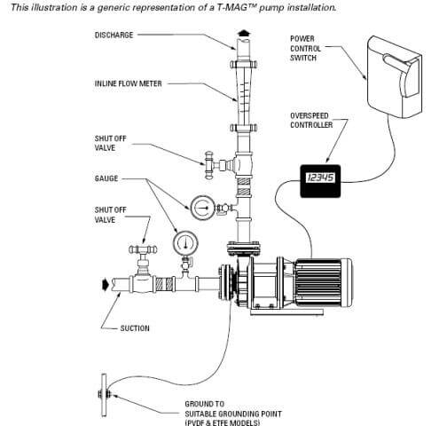
CONTROLS: All pumps should be outfitted with the appropriate safety shut off and controls to meet the local, state or federal requirements for the application in the area the pump is being used. To better understand the performance of the pump it is recommended that gauges be placed on the inlet and discharge lines of the pump, isolation gauges be installed for isolation and repairs and a flow meter be used to monitor the pump’s performance over time.
PUMP DISCHARGE: Be sure that the discharge capabilities of the pump meet the required pressure to overcome the friction loss across the discharge piping, filters and valving. Do not close the downstream isolation valve of the pump while in operation. Doing so will cause the pump head to overheat and may damage the internals of the pump.
PIPING: Final determination of the pump site should not be made until the piping challenges of each possible location have been evaluated. The impact of current and future installations should be considered ahead of time to make sure that inadvertent restrictions are not created for any remaining sites. The best choice possible will be a site involving the shortest and straightest hook-up of suction and discharge piping. Unnecessary elbows, bends, and fittings should be avoided. Pipe sizes and type should be selected to keep friction losses within practical limits. All piping should be supported independently of the pump. In addition, the piping should be aligned to avoid placing stress on the pump fittings. Flexible hose can be installed to aid in absorbing the forces created by the natural vibration of the pump. If the pump is to be bolted down to a solid location, a mounting pad placed between the pump and the foundation will assist in minimizing pump vibration. When pumps are installed in applications involving flooded suction or suction head pressures, a gate valve should be installed in the suction line to permit closing of the line for pump service.
SUBMERSIBLE APPLICATIONS: A T-MAG™ mag drive pump can not be submerged for use.
T-MAG™ MAG DRIVE PUMP : ARE CAPABLE OF PASSING SOLIDS BELOW 5μ (microns), ALTHOUGH ANY SOLIDS WITHIN THE PROCESS STREAM OF A T-MAG™ PUMP COULD WEAR CRITICAL COMPONENTS. THIS WEAR WILL DIMINISH PERFORMANCE OR CAUSE FAILURE OF THE PUMP.